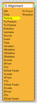
Alignment Operator

Advanced particle animations must have full control of how particles are
aligned in space or in relation to each other. The Alignment
Operator is used to provide this kind of control. A common use of this
operator is to use it for flocking animations in which the particles always
face forward based on the direction of travel. It would look funny if
the birds were to fly backwards, wouldn't it?
This operator is also able to create specific output values that might
be used by other operators.
Operator Inputs
ON - (Bool) This input data stream determines whether
the operator is considered 'on' or 'off'. You can connect other operators
to this input channel such as a Bool Helper to activate/deactivate
the whole operator.
Time - (Time) This input data stream is used to define the local
time for the operator when the user wants to override the default system
time.
Particle - (Particle) This input data stream reads in the currently
selected particle group that is to be used for alignment. The data stream
MUST be connected and will be highlighted yellow if it is not.
To Position - (Position) This input data stream is used to indicate
a User Defined object that the particles should be aligned to.
To Particle - (Particle) This input data stream is used to indicate
another particle group that the particles should be aligned to.
Direction - (Direction) This input data stream is used to override
the User XYZ-Axis controls.
Laziness - (Scalar) This input data stream is used to override
the Laziness spinner value, which determines the swiftness of the particle
to align to a specified vector.
Source - (Integer) This input data stream takes an integer value
that represents the Primary Axis for the alignment. Valid input values
are 0 through 2, where:
0 = X-Axis
1 = Y-Axis
2 = Z-Axis
Invert - (Bool) This input data stream determines whether or not
the Primary Axis is left at it's default (Invert = off), or if the Primary
Axis vector is reversed (Invert = on).
Type - (Integer) This input data stream takes in an integer value
that represents the type of alignment desired. Valid input values are
0 through 7, where:
0 = None
1 = Random
2 = Direction of Travel
3 = World X
4 = World Y
5 = World Z
6 = User Defined
7 = To Particle
Variation - (Angle) This input data stream is used to override
the Variation [*] spinner value, which determines any angular variation
along a user-defined vector.
X / Y / Z Rotation - (Angle) These input data streams are used
to override the angular X/Y/Z Rotation spinner values, which adds a rotational
angle amount to the alignment vector.
X / Y / Z Limits - (Bool) These input data streams determine whether
or not the alignment angle is limited along the specified axis (Bool =
True), or left unconstrained (Bool = False).
X / Y / Z From - (Angle) These input data streams are used to
override the angular limit starting point for the selected axis.
X / Y / Z To - (Angle) These input data streams are used to override
the angular limit ending point for the selected axis.
NOTE: These inputs are provided for future data stream inputs and are not active currently.
X / Y / Z Slide Factor - (Alpha Gradient) These input data streams are used to override the gradients used to determine the acceleration curve used to align the particle to the defined vector.
Operator Outputs
In Focus - (Intensity) This
output data stream can be used to track an object that gets near to the
particle of the connected group. In essence, it uses a Float value to
determine how "good" a value is. 0.0 represents bad alignment,
while 1.0 represents perfect alignment.
Direction - (Direction) This output data stream sends out the
orientation of the particle axis in World Space.
Rollout Menus

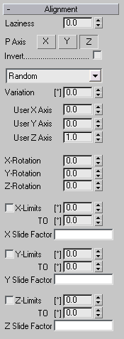
Laziness - In certain situations you will want to force the alignment
of particles to occur over time and not happen immediately. A good example
of this is a cannon on a ship. In order to aim (align) at it's target,
motors must turn to rotate the tower, the cannon itself must be raised
or lowered, etc. This process takes a small amount of time, and the Laziness
value helps mimic this timing. When this spinner is set to zero, particles
will immediately align with their new directional vector, while values
above zero slow the alignment of the particles down by a certain amount.
The higher the value, the longer it will take for particles to align.
P Axis - An alignment operation in 3D space must always have reference
points. This value uses the particle (object) axis for the alignment.
You may choose one of the following axis as the reference of alignment.
X-Axis
Y-Axis
Z-Axis
Invert - Activate this check box to invert the Primary
Axis (P-Axis) to its negative value. Example, X becomes -X and Y becomes
-Y. This check box can come in handy when you are working with instanced
particle objects.
Random - The drop down list offers the following settings:

None - This leaves the particles with their default alignment.
Random - When you select this option, all particles use a random vector.
Direction of Travel - Select this option when you want the particles to align along their movement vector.
World X,Y,Z - With this option selected you may align the particles along the X, Y or Z World Axis.
User Defined - This option must be selected when you want to set a certain direction vector or when you want to use the Input data stream To Position input.
To Particle - Particles can also be aligned in relation to other particles. To use this option, the Input data stream To Particle must be connected to a different particle group.
Variation [*] - Let’s say that you want to align particles
along a user defined vector. Use this value to add some variation to this
fixed vector. The variation ranges from 0-180 degrees.
User Axes - When setting a user defined alignment vector, these
three values are used to define the direction. By default this vector
points Z-Up, or 'up in the sky'.
X / Y / Z Rotation - In addition to a directional vector, you
can also set a certain amount of rotation along the user defined axis.
Limits check box - Particle alignment can be restricted to freely
adjustable angles. The first angle value ([*]) is the minimum angle allowed
and the second angle value (To [*]) is the maximum angle allowed.
Be aware that the Alignment operator locks the particle to this angle regardless of any condition that might change this angle.
Slide Factor - Each axis also provides the ability
fine tune the acceleration curve used to reach the alignment angle. It
is handled with a Slide Factor gradient shown in the rollout. To open
the gradient, simply click on the visible gradient pattern. You will be
presented with the following dialog:

By default, the alignment angle is calculated in a linear manner, but sometimes
it might be useful to have a more mechanical approach, like a big cannon
tower on a warship. It needs some time to accelerate until the target
is in focus. Black color in the gradient means no movement/rotation while
white color represents free rotation/movement that is based solely on
the laziness value. All gray scale values in between represent a percentage
of this free rotation/movement. Electric motors can be easily simulated
by a soft gray scale ramp.
The sliding factor gradient represents the two Limits values (From [*] & To [*]) by dividing the gradient in the middle of its total range (Key value 0.5). From the left most edge to the middle key value you are setting the angular change over time affecting the From value. From the middle key value to the right most edge of the gradient you are setting the user defined acceleration ramp for the To value.